


Easy to add additional units in the future
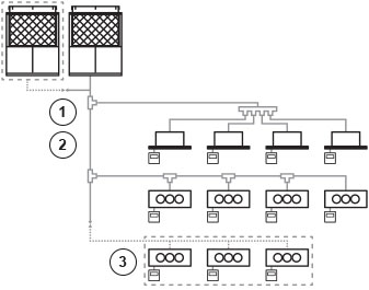
Load can easily be increased in the future by the addition of indoor and outdoor units without having to plumb pipe shafts. When specifying refrigerant pipe work, please choose the size according to the horsepower after the increase of units.
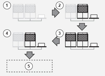
Example of a system. Added outdoor units. (Only for models with the same refrigerant.)
1. If there is a possibility for addition after setting up, please plan it so that the placement of a ball valve (sold separately) on a branch pipe on indoor/outdoor units is possible
2. Main pipe: Maximum gas pipe diameter 38,1 (1 1/2). Maximum fluid pipe diameter 19,05 (3/4)
3. Added indoor units. (Only for models with the same refrigerant.)
Load can easily be increased in the future by the addition of indoor and outdoor units without having to plumb pipe shafts. When specifying refrigerant pipe work, please choose the size according to the horsepower after the increase of units.
Example of a system. Added outdoor units. (Only for models with the same refrigerant.)
1. If there is a possibility for addition after setting up, please plan it so that the placement of a ball valve (sold separately) on a branch pipe on indoor/outdoor units is possible
2. Main pipe: Maximum gas pipe diameter 38,1 (1 1/2). Maximum fluid pipe diameter 19,05 (3/4)
3. Added indoor units. (Only for models with the same refrigerant.)
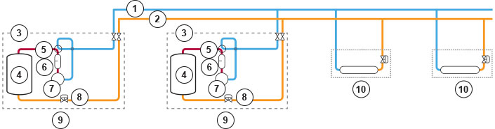
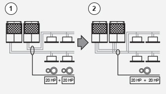
Maximum possible number of outdoor units to be combined: 2 units. Maximum horsepower of combined outdoor units: 50 HP. Maximum possible number of indoor units to be connected: 48 units(1). Indoor/outdoor units capacity ratio: 50%-130%(2).
1. When 2 outdoor units are connected.
2. Capacity of indoor units connection is: Minimum 50% of the capacity of the smallest outdoor unit within the system. Maximum 130%: total capacity of the system outdoor units. Indoor units are same as multi series for buildings.
System diagram: 1. Gas pipe / 2. Fluid pipe / 3. 4 Direction valve / 4. Heat exchanger / 5. Oil separator / 6. Oil-surface sensor / 7. Compresor / 8. Electronic control valve / 9. Outdoor units / 10. Indoor units
Saving Energy
1. Up to this time / 2. W-Multi / 3. Load of around 10 HP (8 h operating) / 4. STOP / 5. Total operating hours: 16 hours / 6. Total operating hours: 8 hours
- Energy savings achieved by the Appropriate Capacity.
- Equational Program Function.
1. Up to this time / 2. W-Multi / 3. Load of around 10 HP (8 h operating) / 4. STOP / 5. Total operating hours: 16 hours / 6. Total operating hours: 8 hours
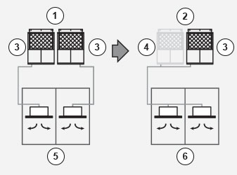
Non-stop operation, even during maintenance
1. Up to this time / 2. W-Multi / 3. System stops during maintenance / 4. Continuous operation under the maintenance / 5. Machine in need of maintenance (maintenance during holidays) / 6. Machine in need of maintenance (maintenance during weekdays) / 7. Backup
- System will not stop even during maintenance, due to Manual Backup Operating Function.
- Maintenance is possible during weekdays because it can continue operating during maintenance.
- Automatic Backup Operating Function enablescontinuous operation.
1. Up to this time / 2. W-Multi / 3. System stops during maintenance / 4. Continuous operation under the maintenance / 5. Machine in need of maintenance (maintenance during holidays) / 6. Machine in need of maintenance (maintenance during weekdays) / 7. Backup
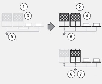
Long lifetime
Example of the rotation function: 1. Operating hours: 2.100 h (unit 1), 2.050 h (unit 2) / 2. System startup. Only unit 2 is operating / 3. Operating hours: 2.100 h (unit 1), 2.053 h (unit 2). Load increased. Units 1 and 2 are operating / 4. Operating hours: 2.105 h (unit 1), 2.058 h (unit 2). Load reduced. Only unit 2 is operating. / 5. Realization of averaging operating hours
- Renewal period prolonged due to rotation function.
Example of the rotation function: 1. Operating hours: 2.100 h (unit 1), 2.050 h (unit 2) / 2. System startup. Only unit 2 is operating / 3. Operating hours: 2.100 h (unit 1), 2.053 h (unit 2). Load increased. Units 1 and 2 are operating / 4. Operating hours: 2.105 h (unit 1), 2.058 h (unit 2). Load reduced. Only unit 2 is operating. / 5. Realization of averaging operating hours
Ease of construction
Example of a system with approximately 40 HP: 1. Up to this time / 2. W-Multi
- By using common header pipe work the installation cost and time is significantly reduced.
Example of a system with approximately 40 HP: 1. Up to this time / 2. W-Multi