New ECO G High Power
GHP with electrical generator. Only consumes 1% of the electricity required by Standard VRF systems!
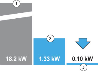
Comparison of electrical consumption on a 71 kW outdoor unit: 1. Standard VRF for 73 kW / 2. ECO G for 71 kW / 3. ECO G High Power for 71 kW. Less than 1% of electrical consumption
Generates electricity during heating or cooling operation
Generates electricity and air conditioning (heating or cooling) at the same time by using remaining engine power. ECO G High Power can generate 2.0 kW electricity at a generation efficiency of more than 40%.
GHP with electrical generator. Only consumes 1% of the electricity required by Standard VRF systems!
Comparison of electrical consumption on a 71 kW outdoor unit: 1. Standard VRF for 73 kW / 2. ECO G for 71 kW / 3. ECO G High Power for 71 kW. Less than 1% of electrical consumption
Generates electricity during heating or cooling operation
Generates electricity and air conditioning (heating or cooling) at the same time by using remaining engine power. ECO G High Power can generate 2.0 kW electricity at a generation efficiency of more than 40%.
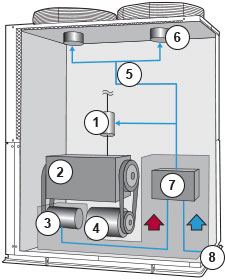
Production of electricity
Generates up to 2 kW depending on air conditioning load.
Panasonic innovates again introducing a new GHP producing his own electricity
Equipped with a small generator of high-performance.
Compressor and generator are driven by gas engine. The generated electricity is used for the fan motor and cooling water pump of its own unit. The generating efficiency is more than 40%.
1. Cooling water pump / 2. Engine / 3. Generator / 4. Compressor / 5. Electricity flow / 6. Fan motor / 7. Electric control BOX (Inverter/Converter) / 8. Electric supply
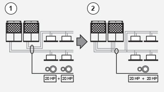
Easy to add additional units in the future
Load can easily be increased in the future by the addition of indoor and outdoor units without having to plumb pipe shafts. When specifying refrigerant pipe work, please choose the size according to the horsepower after the increase of units.
Example of a system. Added outdoor units. (Only for models with the same refrigerant.)
1. If there is a possibility for addition after setting up, please plan it so that the placement of a ball valve (sold separately) on a branch pipe on indoor/outdoor units is possible
2. Main pipe: Maximum gas pipe diameter 38,1 (1 1/2). Maximum fluid pipe diameter 19,05 (3/4)
3. Added indoor units. (Only for models with the same refrigerant.)
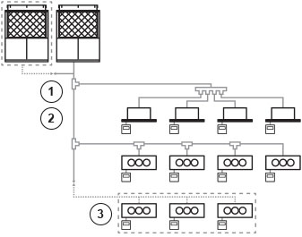
Maximum possible number of outdoor units to be combined: 2 units. Maximum horsepower of combined outdoor units: 50 HP. Maximum possible number of indoor units to be connected: 48 units(1). Indoor/outdoor units capacity ratio: 50%-130%(2).
1. When 2 outdoor units are connected.
2. Capacity of indoor units connection is: Minimum 50% of the capacity of the smallest outdoor unit within the system. Maximum 130%: total capacity of the system outdoor units. Indoor units are same as multi series for buildings.
System diagram: 1. Gas pipe / 2. Fluid pipe / 3. 4 Direction valve / 4. Heat exchanger / 5. Oil separator / 6. Oil-surface sensor / 7. Compresor / 8. Electronic control valve / 9. Outdoor units / 10. Indoor units
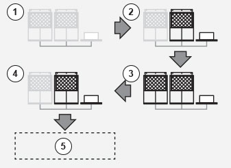
Saving Energy
1. Up to this time / 2. W-Multi / 3. Load of around 10 HP (8 h operating) / 4. STOP / 5. Total operating hours: 16 hours / 6. Total operating hours: 8 hours
- Energy savings achieved by the Appropriate Capacity.
- Equational Program Function.
1. Up to this time / 2. W-Multi / 3. Load of around 10 HP (8 h operating) / 4. STOP / 5. Total operating hours: 16 hours / 6. Total operating hours: 8 hours
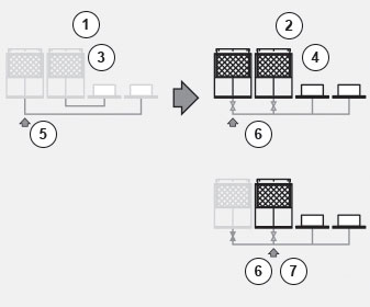
Non-stop operation, even during maintenance
1. Up to this time / 2. W-Multi / 3. System stops during maintenance / 4. Continuous operation under the maintenance / 5. Machine in need of maintenance (maintenance during holidays) / 6. Machine in need of maintenance (maintenance during weekdays) / 7. Backup
- System will not stop even during maintenance, due to Manual Backup Operating Function.
- Maintenance is possible during weekdays because it can continue operating during maintenance.
- Automatic Backup Operating Function enablescontinuous operation.
1. Up to this time / 2. W-Multi / 3. System stops during maintenance / 4. Continuous operation under the maintenance / 5. Machine in need of maintenance (maintenance during holidays) / 6. Machine in need of maintenance (maintenance during weekdays) / 7. Backup
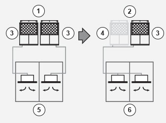
Long lifetime
Example of the rotation function: 1. Operating hours: 2.100 h (unit 1), 2.050 h (unit 2) / 2. System startup. Only unit 2 is operating / 3. Operating hours: 2.100 h (unit 1), 2.053 h (unit 2). Load increased. Units 1 and 2 are operating / 4. Operating hours: 2.105 h (unit 1), 2.058 h (unit 2). Load reduced. Only unit 2 is operating. / 5. Realization of averaging operating hours
- Renewal period prolonged due to rotation function.
Example of the rotation function: 1. Operating hours: 2.100 h (unit 1), 2.050 h (unit 2) / 2. System startup. Only unit 2 is operating / 3. Operating hours: 2.100 h (unit 1), 2.053 h (unit 2). Load increased. Units 1 and 2 are operating / 4. Operating hours: 2.105 h (unit 1), 2.058 h (unit 2). Load reduced. Only unit 2 is operating. / 5. Realization of averaging operating hours
Ease of construction
Example of a system with approximately 40 HP: 1. Up to this time / 2. W-Multi
- By using common header pipe work the installation cost and time is significantly reduced.
Example of a system with approximately 40 HP: 1. Up to this time / 2. W-Multi
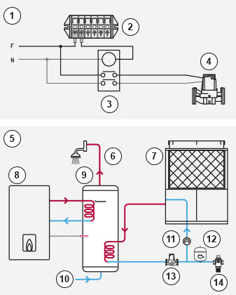
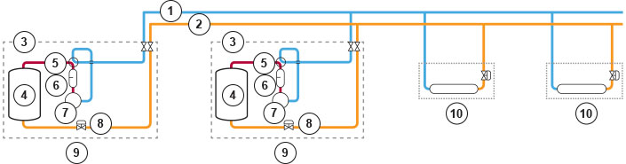
Hot Water Supply Function
Capacity at cooling standard point (outlet temp 75ºC)
Outdoor unit: U-16GE2E5 15.00 kW / U-20GE2E5 20.00 kW / U-25GE2E5 30.00 kW / U-30GE2E5 30.00 kW. Hot water piping allowable pressure 0.7 MPa. Hot water circulation rate 3.9 m³/h. Hot water tube size Rp 3/4
- System Advantage.
Capacity at cooling standard point (outlet temp 75ºC)
Outdoor unit: U-16GE2E5 15.00 kW / U-20GE2E5 20.00 kW / U-25GE2E5 30.00 kW / U-30GE2E5 30.00 kW. Hot water piping allowable pressure 0.7 MPa. Hot water circulation rate 3.9 m³/h. Hot water tube size Rp 3/4
- All the items illustrated in this drawing (except the outdoor unit) are not supplied by Panasonic.
- During start up, set temperature value of the water in the outdoor unit's parameter.